(artname: fgl2a002.EPS)

This chapter briefly describes the functions, capabilities, and benefits of the 8275 Model 416 High Performance Ethernet Workgroup Switch. This information helps you to plan for and use the switch in your network.
Fast Ethernet switching continues to evolve from high-end backbone applications to desktop-switching applications. The switch provides a low-cost and powerful Layer 2 switch solution. It is an attractive base switch offering with the following key functions:
As a network administrator, you have a choice of three easy-to-use management methods: VT100 terminal interface, Web-based, and Simple Network Management Protocol (SNMP). These management methods enable you to configure, manage, and control the switch locally or from anywhere on the network.
The Spanning Tree Protocol (STP) provides fault tolerance on the network.
This section describes the functional support included in the switch:
The 8275-416 is a Layer 2 Ethernet switch in which frame forwarding is based on MAC addresses and VLAN membership. The switch supports the IEEE 802.1D (1998) and 802.1Q standards.
The switch supports 802.3x flow control, which, when enabled, allows the transmission of data frames to be inhibited for a specified period of time. The default for 802.3x flow control is Disabled. 802.3x flow control is valid only when the port is in full-duplex mode.
The switch detects broadcast storms and automatically blocks broadcast traffic to minimize the impact of the broadcast storm on the rest of the network. You can enable or disable this function at a switch level. For all broadcast frames received by the switch, the broadcast storm recovery operation depends on port speed and is described as follows:
The switch port MAC addresses are stored in the forwarding database. An address learned by the switch is removed from the forwarding database after a period of time if no frames have been received from that address. The default value for the aging period is 300 seconds (5 minutes), but it can be configured by the user. The time values range from 10 seconds to 600 seconds.
The switch forwarding database stores 12 000 entries. When the database is full, no new entries are learned until an existing entry ages out. All frames with unknown destination addresses are multicast to all ports in the appropriate VLAN.
The switch supports VLANs. Appendix E, Introduction to Virtual LANs (VLANs) provides an introduction to VLANs. It describes concepts and terminology, as well as, the benefits of using VLANs. The switch is manageable only through the ports which are members of the Default VLAN (VLAN 1).
Figure 36 and Figure 37 show examples of the panels and descriptions of the parameters used to configure VLANs.
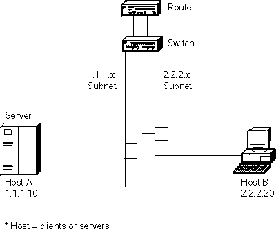
Self Learning IP is a configurable function of the switch that learns where IP addresses are in the network so that packets normally sent from one host to another through a router can bypass the router and be sent directly to the destination host address. Self Learning IP is most effective when the switch is used to "front" the router (the switch is positioned logically between the router and the networks to which it belongs). Because of this strategic vantage point in the network (Figure 1), the switch has visibility to all packets flowing to and from the router, as well as between any two switch ports. The switch monitors the traffic to determine if a Layer 2 shortcut can be used instead of subjecting the packet to Layer 3 router processing which can be relatively lengthy.
Figure 1. Self-Learning IP in the network
 (artname: fgl2a002.EPS) |
The Self Learning IP function essentially:
Device learning and classification is accomplished by watching ARP replies that flow naturally through the switch with the addition of active probing to determining whether a device is a router or a host. When an IP packet enters the switch, the Self Learning IP function compares the destination MAC address against the list of known routers, then checks if the destination IP address is a known host. If both tests pass, the packet is automatically re-addressed to the destination IP host device and is sent out the appropriate switch port.
A Router Table and Host Table are used to manage information learned about router and host devices, respectively. To keep this network information current, the Router Table entries are refreshed every 5 minutes while Host Table entries are checked every 3 minutes. Devices which are no longer active are dropped from their table; devices may be relearned at a later time as conditions change.
To use the Self Learning IP function, the switch must be configured with the following:
Once Self Learning IP is enabled, the following information is available:
Note that the Packets Switched count included in the Switch Detailed Statistics Menu may not reflect the absolute latest value. The information used for updating this count is obtained as individual Host Table entries are refreshed, so while this value can change over time, it does not necessarily update at the same frequency as other statistics on the menu.
While intended as an autonomous feature, Self Learning IP is affected by certain changes in switch configuration. If Self Learning IP is enabled and the switch IP address is reset, the Self Learning IP function is automatically disabled. The Self Learning IP Router and Host Tables are cleared whenever there is a link aggregation configuration change (see Link aggregation (trunking) in this chapter), forcing router and host devices to be relearned.
Link aggregation, also called trunking allows 802.3 MAC interfaces to be grouped together logically to appear as one super-link. The super-link or Link Aggregation Group (LAG) has access to the combined bandwidth of all links.
The Sun Trunking(TM) 1.0 specification is supported for the 10/100BASE-TX and 100BASE-FX ports. All members of the trunk must support Sun Trunking(TM) 1.0. For information about configuring trunks, see Trunk management menu. Up to 8 trunks can be configured.
Advantages of trunking are:
The IEEE 802.1D spanning tree protocol (STP) is designed to prevent loops in Ethernet networks. To achieve this objective the STP does not allow switches to forward data frames on a link immediately after the link is activated. The STP first listens for spanning tree BPDUs from other switches, then determines whether to put the link into forwarding state. When a default IEEE spanning tree timer value of 15 seconds is used for the forward delay timer, a link can start forwarding traffic 30 seconds after it becomes active on the network.
In networks with shared media hubs, there is a trend to attach network stations (or hosts) directly to multi-port bridges (otherwise known as switches). Unfortunately, the 802.1D spanning tree protocol has not been changed to accommodate this trend. So, when a network station is ready to send data, the switch does not allow the network station to communicate on the network until STP puts the port in forwarding state. The 30 second delay forces the network station users to wait longer before accessing the network. Even worse, some higher level protocols running on the network station may time out, generate error messages or not work at all.
The 802.1D standard specifies that when a link comes up on the network, the spanning tree state is set to "Listening". After the forward delay timer expires, the spanning tree state is set to "Learning", and after another forward delay timer interval the state is set to "Forwarding". The forward delay timer is set for the entire network by the root bridge. The default value for this timer is 15 seconds.
With the Fast Spanning Tree function, the transition from "Listening" to "Learning" and the transition from "Learning" to "Forwarding" takes approximately 6 to 8 seconds. The forward delay timer behavior reverts to the 802.1D standard (15 seconds) after a port goes into forwarding state or blocking state.
Fast Spanning Tree mode is configurable by port. The default is the standard 802.1D protocol. When a port is configured in Fast Spanning Tree mode, it takes approximately 6 to 8 seconds before traffic can be forwarded on the link. Spanning tree can also be disabled on the port. For details about configuring ports for Fast Spanning Tree mode, see the Port Configuration Menu in Chapter 4.
| Note: | The switch is manageable using the Ethernet network only through the ports which are members of the Default VLAN (VLAN 1). |
You have a choice of these easy-to-use management methods:
Accessing the switch describes how to access the switch using this interface and Using the Terminal Interface instructs you about using this interface.
Accessing the switch describes how to access the switch using this interface and Using the Web Interface instructs you about using this interface.
User access security can be implemented using the following functions of the 8275-416:
The switch:
High performance, Layer 2 switching for the switch consists of:
The 8275-416 is Y2K compliant.
When used in accordance with its associated documentation, it is capable of correctly processing and/or receiving date data within and between the 20th and 21st centuries providing all other products (for example, hardware, software, and firmware) used with the switch properly exchange accurate date data.
For additional information about Year 2000 related topics, visit:
http://www.ibm.com/year2000
Ethernet cables are not provided and must be separately purchased. You can order them through your IBM representative.
Table 1 shows cable type and length requirements. Cable
requirements depend on the speed of the network. Cables and connecting
hardware must meet the standards specified in the ANSI/TIA/EIA 856-A or CSA
T529 standards.
Table 1. Ethernet cable requirements
| Ethernet Type | Cable Requirements | Max. Cable Length |
|---|---|---|
| 10BASE-T | Category 3, 4 or 5 100-ohm STP/UTP cable | 100 m (328 ft) |
| 100BASE-TX | Category 5, 100-ohm STP or UTP cable and connecting hardware | 100 m (328 ft) |
| 100BASE-FX | 62.5-micron multimode fiber (MMF) cabling | 2 km (6561 ft) at full-duplex; 412 m (1352 ft) at half-duplex |
| 1000BASE-SX | 50/125-micron or 62.5-micron multimode fiber (MMF) cabling | 550 m (1804 ft) at full-duplex. |
Do not use telephone extension cables in 10/100BASE-TX networks. The wire pairs in those cables are not twisted and the cables do not meet other requirements for use in a 10BASE-T network.
For connections to 10/100BASE-TX networks, you can use only Category 5 STP or UTP cables.
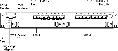
Figure 2. Front panel of the switch.
 (artname: fgb0a001.EPS) |
See Accessing the switch for more information about connectivity.
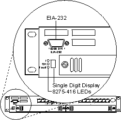
Switch LEDs are shown in Figure 3 and LED status is explained in the table that follows:
Figure 3. LEDs for the switch.
 (artname: fgb0a018.EPS) |
Table 2. LED status for the switch.
| LEDs | Explanation | ||
|---|---|---|---|
| I (Green) | OK (Green) | Fault (Yellow) | |
| Off | Off | Off | No power is present, or there is a power supply failure. The switch is not operational. |
| On | On | Off | The switch is operational. |
| On | Blinking | Off | Configuration file or Operational Code file transfer is in process. Do not power-off or reset the switch. |
| On | Off | On | There is a hardware fault. The switch is not operational. |
| On | Off | Blinking | Diagnostics are in process. The switch is not yet operational. |
| Note: | Any other state of the LEDs indicates an LED failure. |
The single-digit display (shown in Figure 3) displays characters while diagnostics are running after
power is applied to the switch. At the successful completion of
diagnostics, the unit number appears in the display (for example, "1"
indicates Unit Number 1). Table 3 gives the meaning of other digits that can be displayed and
the corrective actions required.
Table 3. Problem indications on the single-digit display when the Fault LED is ON.
| Character | Problem | Corrective Action |
|---|---|---|
| d | Board RAM problem | Replace the switch. |
| 3 | Detected an unsupported feature module. | Remove the feature module and update the operational code, or the feature module is not fully seated in its connector. |
| 4 | PIF fault on the feature module or base board. | If feature module Fault LED is On, remove the feature module. If no feature module Fault LED is On, replace the switch. |
| 5 or 6 | Non-volatile memory problem. | Replace the switch. |
| 7 | Switch memory problem. | Replace the switch. |
| 8 | Base board loopback problem. | Replace the switch. |
| 9 or a | Feature module loopback problem. |
|
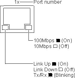
The switch has 16 base 10/100BASE-TX ports. LED status for these 16 base ports are shown in Figure 4 and they are explained in Table 4.
Figure 4. LEDs for the base 10/100BASE-TX ports on the switch
 (artname: fgb0a021.EPS) |
Table 4. Status of LEDs for 16 base 10/100BASE-TX ports
| LED | Color | State | Explanation |
|---|---|---|---|
| Right Ethernet Port LED | Green | ON | Indicates a 100-Mbps port. |
|
| OFF | Indicates a 10-Mbps port. | |
| Left Ethernet Port LED | Green | ON | The link is up. |
|
| OFF | The link is down. | |
|
| Blinking | Transmitting (Tx) and Receiving (Rx) traffic. | |
Each feature module has an OK and a Fault LED located at the left side of the faceplate. The OK LED is green and the Fault LED is yellow. LED locations are shown in Figure 5, Figure 6, Figure 7, and Figure 8; LED status of the feature modules are explained in Table 5, Table 6, Table 7, and Table 8.
Figure 5. LEDs for the 8-port 10/100BASE-TX feature module.
 (artname: fgb0a019.EPS) |
Table 5. Status of LEDs for 8-port 10/100BASE-TX feature module
| LED | Color | State | Explanation |
|---|---|---|---|
| OK | Green | ON | There is power to feature module. |
|
| OFF | There is no power to feature module, no power to the switch, or the module has failed. | |
| Fault | Yellow | ON | There is a module fault. |
|
| OFF | There is no module fault. | |
| Right Ethernet Port LED | Green | ON | Indicates a 100-Mbps port. |
|
| OFF | Indicates a 10-Mbps port. | |
| Left Ethernet Port LED | Green | ON | The link is up. |
|
| OFF | The link is down. | |
|
| Blinking | Transmitting (Tx) and Receiving (Rx) traffic. | |
Figure 6. LEDs for the 8-port 100BASE-FX feature module.
 (artname: fgb0a020.EPS) |
Table 6. Status of LEDs for 8-port 100BASE-FX feature module
| LED | Color | State | Explanation |
|---|---|---|---|
| OK | Green | ON | There is power to the feature module. |
| OFF | There is no power to the feature module, no power to the switch, or the module has failed. | ||
| Fault | Yellow | ON | There is a module fault. |
| OFF | There is no module fault. | ||
| Port LED | Green | ON | Link is up. |
| OFF | Link is down. | ||
| Blinking | Transmitting (Tx) and receiving (Rx) traffic. |
Figure 7. LEDs for the 4-port 100BASE-FX feature module.
 (artname: fgb1a001.EPS) |
Table 7. Status of LEDs for 4-port 100BASE-FX feature module
| LED | Color | State | Explanation |
|---|---|---|---|
| OK | Green | ON | There is power to the feature module. |
| OFF | There is no power to the feature module, no power to the switch,or the module has failed. | ||
| Fault | Yellow | ON | There is a module fault. |
| OFF | There is no module fault. | ||
| Port LED | Green | ON | Link is up. |
| OFF | Link is down. | ||
| Blinking | Transmitting (Tx) and receiving (Rx) traffic. |
Figure 8. LEDs for the 2-port 1000BASE-SX feature module.
 (artname: fgl2a001.EPS) |
Table 8. Status of LEDs for 2-port 1000BASE-SX feature module
| LED | Color | State | Explanation |
|---|---|---|---|
| OK | Green | ON | There is power to the feature module. |
| OFF | There is no power to the feature module, no power to the switch,or the module has failed. | ||
| Fault | Yellow | ON | There is a module fault. |
| OFF | There is no module fault. | ||
| Port LED | Green | ON | Link is up. |
| OFF | Link is down. | ||
| Blinking | Transmitting (Tx) and receiving (Rx) traffic. |
Table 9 summarizes the physical characteristics for the
switch:
Table 9. Summary of physical characteristics for the switch